I decided to have the wings folded, so this makes the wing centre-section the core of the project. I compared the cast resin wheel well from both kits and decided to go with those from the Grand Phoenix kit. Both had similar levels of detail and the PP Aerokits had some nice etched metal details. The final decider was, that it would be easier to cut back the outboard sections of the GP parts, than the PP part, to accommodate the work that will be required to detail the visible section of inboard wing with the wings folded.
First I fitted the wheel wells. This entailed quite a bit of grinding to get a good fit to the lower wing surface and, the removal of a lot of excess material from the top of the wells so that the upper wing moulding would fit. (They were ground within a micrometer of their life, becoming translucent in places. I did the grinding outside and had to wash the mask filter afterwards!) Using the two part GP wheel wells also enabled me to put in a spar to hold the wing centre section at the correct dihedral.
The plastic of the PP parts is quite thick which, while giving the parts excellent strength, does mean quite a lot of grinding and filing involved to open up the radiator intakes and cut open the exhausts. To ensure that I was getting each intake the same, and with an even opening, I taped the upper and lower wing halves together to help with the Mk.1 eyeball judgement.
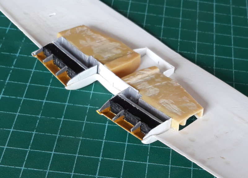
I also decided to do a bit of work and make the coolant radiators a bit more realistic. The PP kit includes no radiators and suggests merely to add the flow dividers and to paint the front face of the wheel well black. This would place the 'radiator faces' too far aft, so I decided to make more representative radiators and place them in the correct position. As an aerodynamicist, I have always abided by the basic principle that "what goes in must come out", so, I also elected to open up the radiator exits.
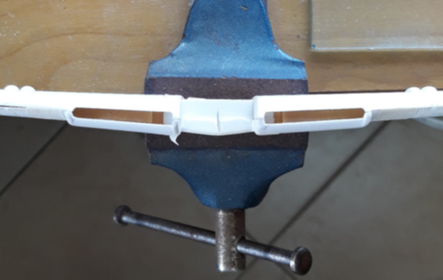
Next step was to make the intake duct walls and fit them. Then followed the radiators and flow dividers, which were fitted to the lower wing. I then added the exit duct section and painted the intake duct and the flow dividers. Photos of the aircraft I am modelling indicated the lower section was painted yellow and the upper section aluminium.
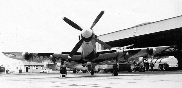
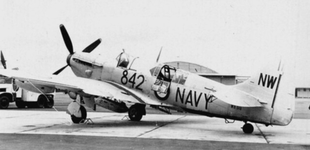
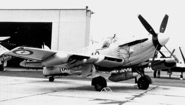
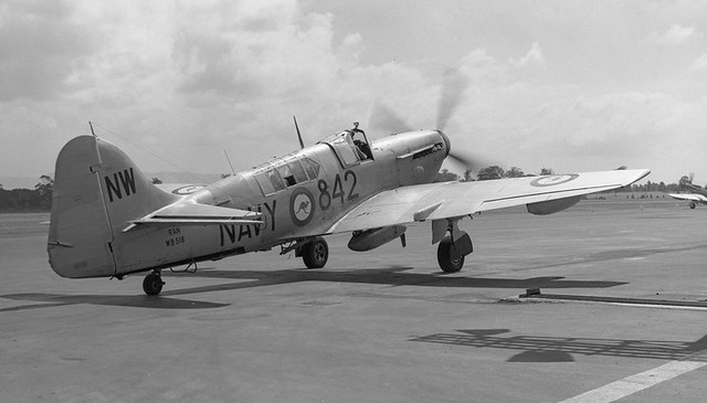
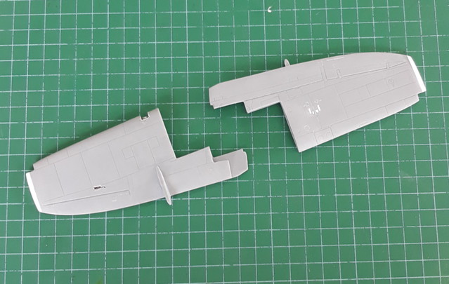
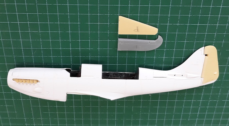
Next step, cut off the wing outer panels. And this is the aircraft I was trying to model.
As mentioned earlier, I wanted to fold the wings, so next step was to cut off the outer wing panels. As I had the etched metal, wing fold, set from Airwaves, I decided to use the outer wing panels from the Grand Phoenix kit as the instructions stated it was for this kit. (I am aware that Wolfpack do a resin kit for the wing fold but rejected using it as (a) it is intended for the Special Hobbies kit and may not fit here, (b) it's price was too much for my wallet and, (c) it would not fit into my timeline). Gun barrels were removed from the wing and the shell ejection chutes filled in.

The Airwaves kit turned out to be a bit of a disappointment. It is rather two dimensional, and ignores the fact that there is a big 'ole under the fuselage when the wings are retracted. A quick check showed that it will only fit the wing outer panels with a bit of work to pack them up to thicker section. I decided that I would do a bit of scratch building to get a more accurate, three dimensional, effect on the wing centre section. It may be possible to use some of the Airwaves bits on the outer section with some extra scratch built bits - lugs, locks, control connecting rods etc. There are no parts from the Airwaves kit in the pic below, just plasticard, sweat and tears.
Photos available on the Walk Around section on the Britmodeller site, (thanks @Julien), and shots taken over the years by myself and @RAL of the aircraft held by the Camden Air Museum were of great help in this phase.
While the glue was drying, I took the opportunity to shorten the wing tips to the Mk. 5/6 style and add the cut outs for the nav/positioning lights, the landing light and, the recess where the wing steady fitted.
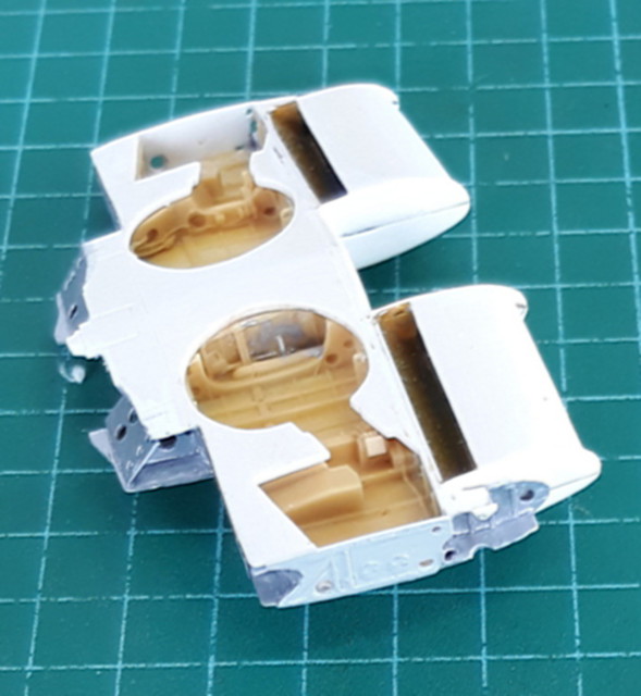
I used a combination of parts from the Grand Phoenix kit and the PP Aerokit, to make up the pilot's and observer's positions. The former was mainly GP and the latter mainly PP. I also added quite a bit of scratch built parts to enhance the observer's position and modify it for TT duties. At this stage I have only installed the parts below the 'bench' in the observer's position, as my ham-fisted efforts would probably break off anything that was above this, while I did other work on the fuselage.
Before joining the fuselage halves, I fitted the resin exhausts from the GP kit. The cast metal exhausts from the PP Aerokit were quite nice but the idea of using only two parts compared the fourteen parts of the PP kit appealed. I fitted the front bulkhead that holds the mounting for the propeller and opened up the cooling intakes on top of the engine cowling.
Cut outs were made for the recesses where the wing support struts retract, as the struts will be extended on my model. A little measuring showed that the arrestor hook arms were too close together and I would not be able to install the flare/target chute. I cut out the offending area from the PP kit and replaced it with the corresponding section from the GP kit. It fitted a lot better than I expected. I then cut out the section where the flare/target chute was to go and fitted the cast metal part from the PP kit, topped with sheped plastic tube to extend it into the observer's position.
Mk. 1 eyeball indicated that the rudder post appeared to have forward sweep. I knew that, aerodynamically, this was to be avoided if possible. Consulting the excellent set of Firefly drawings and dimensions published by Ian Huntley in his column, way back some 30 years ago, showed that my assessment was correct. This in turn meant that the fin area of the PP kit was not quite correct as the forward sweep gave a reduced area and height. I fitted wedge shaped pieces of plasticard to correct that and also added a piece to the base of the rudder to correct its height to match the modified fin.
I also drilled holes to carry spars on which to mount the tail planes. I decided to have the elevators slightly drooped so modified parts from both kits to achieve this. The fuselage was now ready to be joined up.
After this I did a trial fit of the wing centre section to the fuselage and realised that I had stuffed up and cut out too much from the fuselage wing root area. Annoying, but nothing that a bit of plasticard and some filler can't fix. A fair bit of filler is also going to be required at the wing LE to fuselage join.


Next step is to fill that big black 'ole under the fuselage at the wing trail edge. When the wings of the Firebox were retracted, she dropped the veil and showed all. The Airwaves conversion kit gives a 'modesty' curtain to fit here, but it is wrong, all is on display.
Click on the 'Next' button to go to Page 3 of the article