Airship Kits
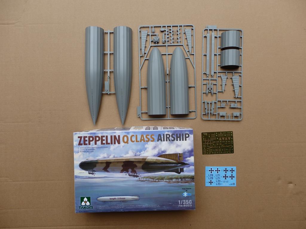
After a lifetime of working in the One True Scale, I realised that any airship model would have to be to a much smaller scale. Therefore, with some trepidation, I purchased examples of the recent Takom "P" and "Q" Class Zeppelins in 1/350th scale - Photograph 1 shows the injection moulded parts, decal sheet and, in my view, the totally useless etch-brass fret of a "Q" Class kit. With either of these kits a world of conversions to various Zeppelin and even Schutte-Lanz airships has become possible (the Mark I kits in 1/720th scale and the Takom offering in 1/700th scale are available for those with better eyesight and more dexterity than the author).
Modelling LZ.VI
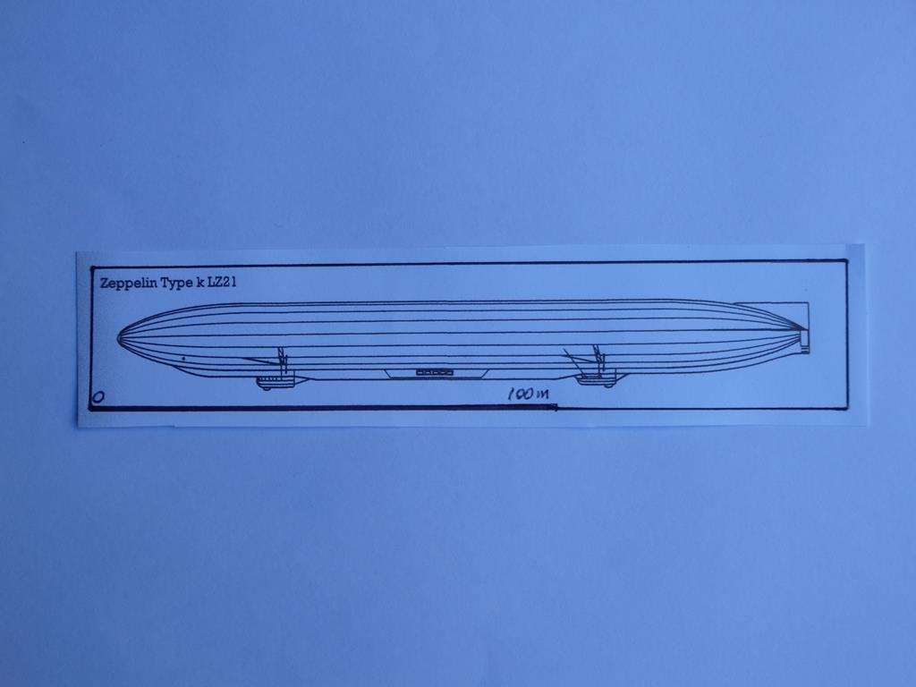
An artist's impression of Zepellin LZ.VI a "k'' Type ship (note that the profile is to 1/700th and the scale bar)
The "k" Type ship was substantially different to the "P" Class, so the following changes need to be made:
Hull;
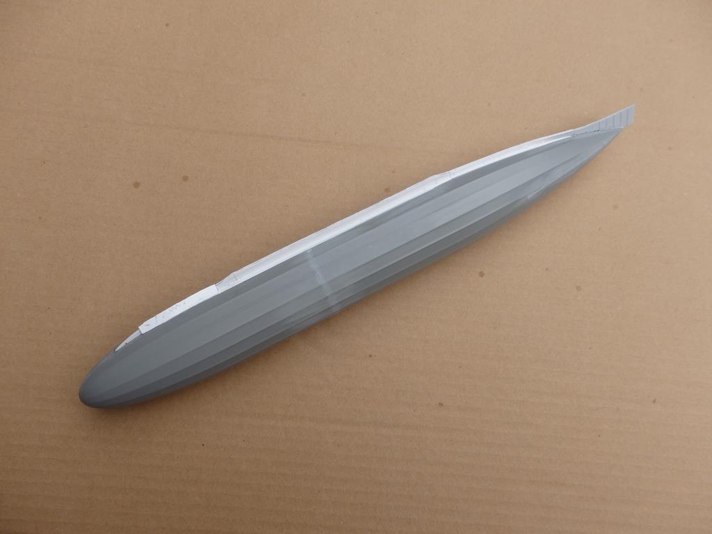
The hull of the "k" Type was 14.9m in diameter (43mm in 1/350th scale) so both the hull halves must have 5mm removed top and bottom. It was also shorter therefore 44mm must be cut from the centre of the hull - the new hull sections will require stiffeners internally. There was a triangular section external keel, 4mm deep fore and aft and 6mm deep between the gondolas and flairing into a small fin at the rear of the hull which must be fabricated from plasticard and detailed with strip/rod. This fin extends 5mm past the end of the hull. The five bomb-bay doors each side at the centre of the deeper section are 4 x 3mm each – scribed or represented by thin plasticard. Lastly the machine-gun pit on the top and the recess in the bottom of the hull must be filled.
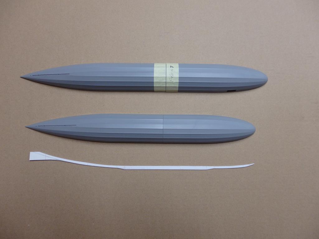
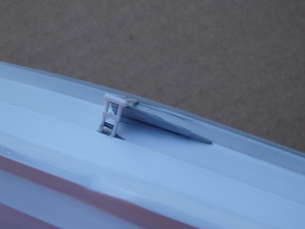
One half of the hull shortened and plasticard keel centreboard.
Internal stiffening.
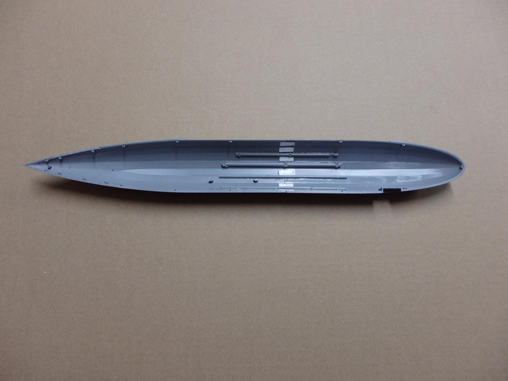
Triangular keel under construction. Note ventral fin.
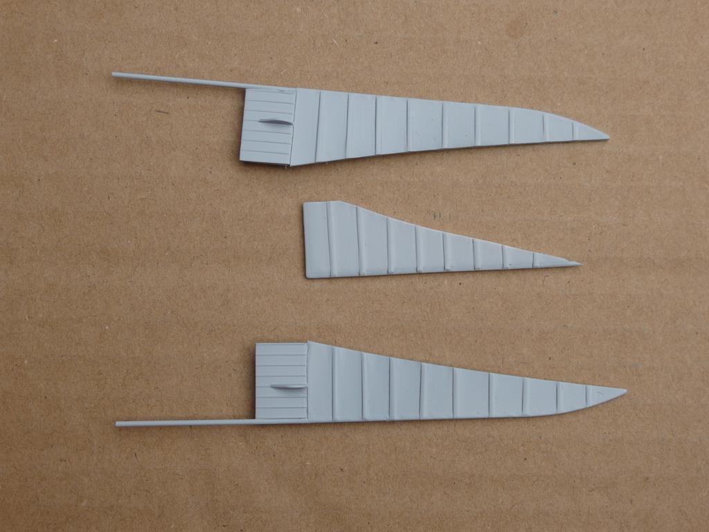
Dorsal fin and horizontal fins & elevators.
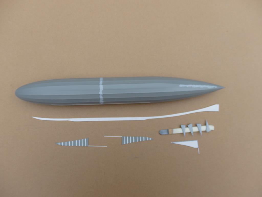
Shortened hull, keel and control surfaces.
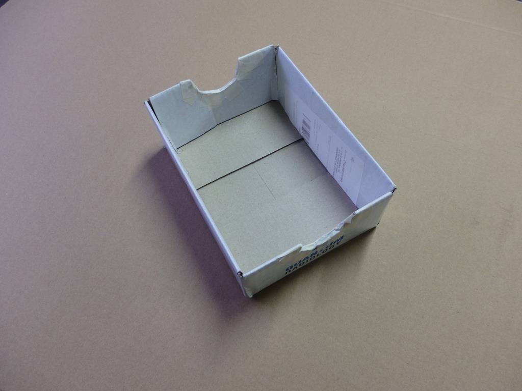
Temporary jig to hold hull.
Propeller Mounts (x 4);
Each consists of a 24 x 9mm triangular fin cut from plasticard and detailed with strip/rod, with two horizontal and two diagonal braces to the hull from Evergreen rod, onto which is mounted a 3mm length of rod (representing the gearbox) and the kit propellers. Finally there is a drive-train with two braces from the motor in the gondola to the gearbox, again from rod.
Gearbox mount 1.

Gearbox mount 2.
Click on the 'Next' button to go to Page 3 of the article